The use of internet of things (IoT) technologies in urban environments optimizes and automates urban processes, making cities safer, more efficient and more comfortable places to live. IoT programmable logic controllers (PLCs) can collect information from individual sensors, connected engineering systems and other equipment, and send it to cloud platforms and applications for further analytics.
At the same time as forming the boundary between the physical and digital worlds, such devices are a cybersecurity bottleneck. By hacking them, cybercriminals get to directly impact processes in the physical world, as well as gain access to, or modify, sensitive data. From the IT loop, they thus infiltrate the OT (operational technology) loop.
We took a typical PLC for a smart city and, together with the manufacturer (ISS), made it Cyber Immune, that is, guaranteed to achieve the set security goals, even under attack. This was a major step toward realizing the potential of the smart city concept, while avoiding the associated critical cyber-risks. This post explains exactly what we did and why, and how it helped to eliminate the cyber-risks.
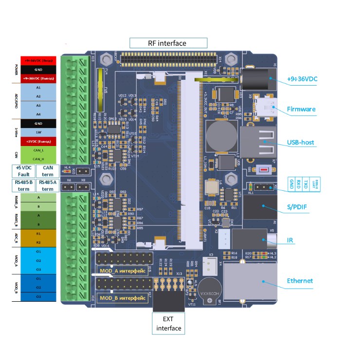
For the hardware part, we took a fairly typical PLC with an ARM9 processor, which looked as follows:
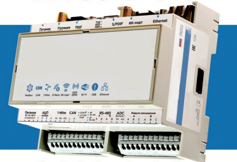
The PLC communicated with top-level cloud platforms and applications via Ethernet, and with field devices via RS-485.
The PLC was Debian-based and designed to handle the main operation scenarios of the device:
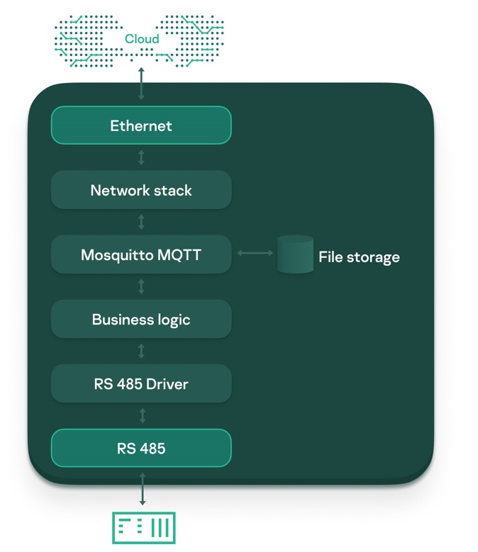
To implement these use cases, the PLC architecture was kept quite minimal. It consisted of several components, the main one being a Mosquitto message broker for sending and receiving data via the MQTT protocol. This component formed the heart of the first build, since it channeled all information flows:
Schematically, the architecture can be represented as follows:
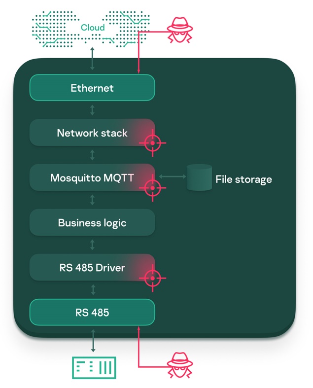
Looking at the PLC from a security perspective, we can identify a number of fundamental problems:
In practice, the above issues greatly increase the information security risks, as they can not only make an incident more likely, but also more damaging. The burden on the operating unit also increases – if the vendor releases a patch for a vulnerability, the administrator must respond immediately and update the device.
Our task was to make the solution Cyber Immune. That meant designing the system so that the properties we identified as important were maintained under all circumstances, even in the event of a cyberattack. To do so, we had to address the fundamental issues outlined above.
The first thing we did was to define what security meant in our particular case by posing the question: What are we protecting the PLC from? That is, we formulated the security goals and assumptions. The security goals were those invariant properties which, if achieved, would ensure the safe operation of the system in any possible use case, factoring in the security assumptions. The security assumptions consisted of additional constraints imposed on the operating conditions of the system.
Next, we designed the PLC architecture so that the stated security goals would be met without fail, taking into account the safety assumptions. To achieve this, we modified the architecture of the original PLC.
Above all, it was necessary not only to bulletproof the system at the application code level, but also at the deeper level of the operating system. For this reason, our first step in designing the architecture was to migrate the solution from Debian to KasperskyOS, which meets the requirements for out-of-the-box Cyber Immunity.
That done, we adjusted the architecture of the application part of the PLC, eliminating the fundamental architectural problems discussed above: we isolated the MQTT broker, separated the upstream and downstream data flows, and improved administration security.
The result was a Cyber Immune system guaranteed to achieve the security goals, as we have verified through multiple tests and checks.
Now let’s review the steps we went through in order.
The Cyber Immune approach is based on the Secure by Design philosophy, which states that the security of a system is not an additional requirement, but an integral part of its design. That is, security must be built in at the design stage.
At the same time, Secure by Design in its purest form says little about the specifics of how to achieve this.
This is where Cyber Immunity comes in, which adds flesh to the bones:
Putting the Cyber Immunity approach into practice, the first step was to formulate an answer to the question: What are we protecting the PLC from? That is, to explicitly describe the PLC values and potential troubles unacceptable for us – at the level of the product’s business purpose.
We realized that we needed:
These were the things that we decided must be protected from potential problems. And not from specific vulnerabilities or attack scenarios. We proceeded from the premise that “everything that can be hacked will be hacked.” That is, any violations of the aspects outlined above are unacceptable for us, be they known vulnerabilities or zero-days that appear later.
Defining what’s important for us underpins our understanding of what system security actually is. After all, there is no thing as “general security.” Security is always specific to each product depending on its business purpose and context of use. Aiming at general security means trying to make the system invulnerable by protecting every single component from every single threat (which is impossible, not least due to limited resources).
Instead, the Cyber Immune approach introduces security goals and assumptions. With this in mind, we documented the above-described values in more formal language in the form of security goals.
In summary, the security goals for the PLC look as follows:
In defining the security assumptions, we set a number of restrictions. In particular, we defined and identified:
• Constraints on physical access to the PLC
• Potential actions by internal and external intruders
• Trusted configuration sources
• Threats that we do not provide protection against (for example, we accepted that we do not protect against anthropogenic threats)
The next important step was to design the system so as to deliver the set security goals, taking into account the security assumptions. To achieve this, we modified the architecture of the original PLC. Let’s take a look at what we did and why.
Trust in the system level of the solution is essential – without it all further efforts to build a secure system as a whole will be futile. So, the first design step was to port the solution from the original Debian operating system to KasperskyOS, which meets the requirements for out-of-the-box Cyber Immunity. Due to support for most POSIX calls and the large variety of basic components in the SDK (for example, network and file subsystems), porting did not entail a complete rewrite of the entire code.
The main task that was addressed was to switch the administrative data flow (the way components interact within the solution) from the MQTT protocol to IPC (interprocess communication – the core mechanism of interaction within KasperskyOS). This solved several tasks at once:
Accordingly, the NEAT principle was observed:
• Non-bypassable – protection mechanisms cannot be bypassed
• Evaluatable – all security policies are stored inside the monitor, able to be easily analyzed and verified as correct and sufficient
• Always-invoked – security policies are applied to any interaction in the system
• Tamperproof – the system cannot be modified during operation
After protecting the system layer, we also needed to secure the solution’s application layer. This began by analyzing the central component of the whole solution: the MQTT broker.
The MQTT broker has the largest attack surface (due to its large codebase and interaction with the external network), and its correct operation underpins the whole solution. This component also implements a TLS connection – the main mechanism for secure interaction with the cloud.
What’s more, the MQTT protocol contains almost no security features: the MQTT 5.0 specification contains only general recommendations for the developer. Above all, this jeopardizes the security goal for communication with the cloud platform, but it is also a security bottleneck in attacks on other system components and, thus, a violation of the other security goals.
To increase broker security and simplify the procedure for verifying the correctness of the TLS connection, there was no need to invent some kind of on-the-spot protection; instead, we used one of the many KasperskyOS design patterns: TLS Terminator.
Design patterns are replicable architectural constructs that address common design issues within some frequently occurring context.
The TLS Terminator pattern provides for the use of a separate component to establish the TLS connection, which:
The result is the following communication pattern:
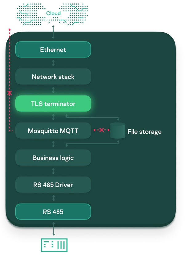
That is:
On top of that, we maintain strict control over all interactions with TSL Terminator as per the security policies, which have been flexibly configured specifically for this component.
As a result of the work carried out, the attack surface of the MQTT broker seen by an intruder in the external network was drastically reduced, and verification of the TLS connection mechanism was simplified.
The next step was to separate the flows of data coming from the cloud (control data flow) and telemetry data collected from field-level execution units (field data flow).
This was accomplished as follows:
The outcome was the following communication pattern:
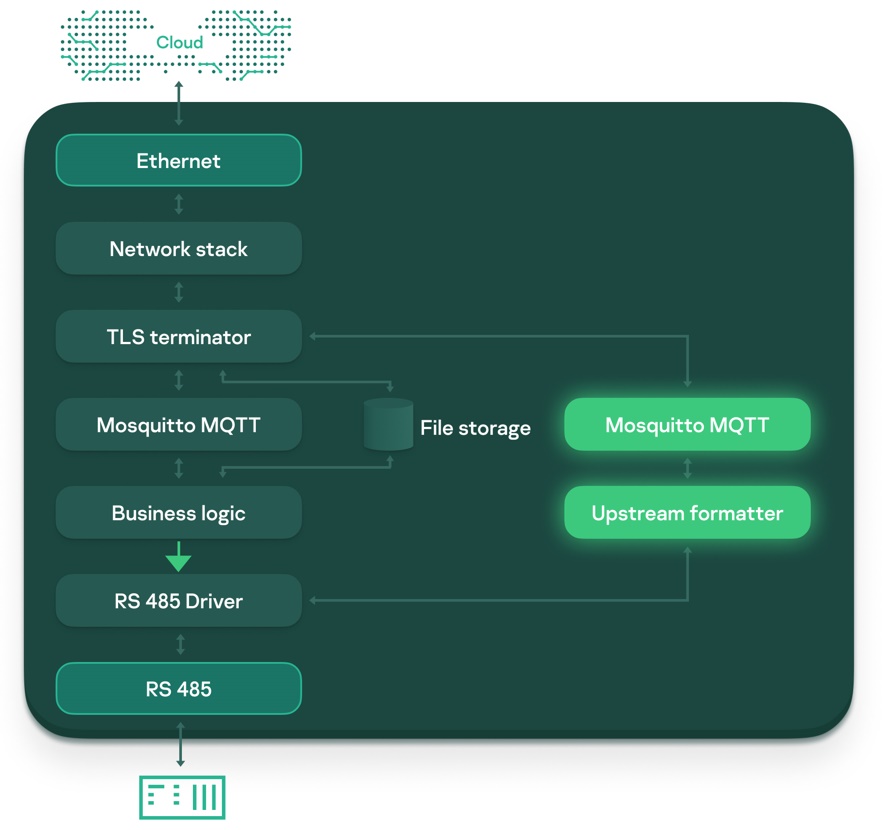
As a result of the work carried out, the device was protected from attacks by an intruder in the internal network.
One of the customer’s main requirements for the smart controller was usability. For this purpose, a web server was deployed on the device, providing the administrator with a wide range of options. However, from a security perspective, the web server, like the MQTT broker, is a highly vulnerable component that requires protection.
A particularly important security goal for the PLC is to ensure secure administration of the device. But how is this administration organized? For example, when diagnosing the device status, an authorized user sends a request to the web server. The web server, in turn, forwards a diagnostic request to the components to share their status and then sends the result back to the user. When updating configurations, the web server passes the dataset to the component responsible for validating and installing the update package. So, by hacking the web server that has a large attack surface, an attacker can cause damage to other components of the solution.
By isolating the web server in a separate component, we solved multiple issues related to privilege escalation, but the question of administrator authorization remained. Most reliable is certificate-based authorization, but implementing this mechanism in the web server itself gives rise to the same issues as when using TLS in the MQTT broker.
To solve this problem, we also used the TLS Terminator pattern, but not in the client version (which establishes a connection at the request of the component), but in the server version.
The server version of TLS Terminator (also based on Mbed TLS) makes it possible to deploy a server available for connection from an external network using the TLS protocol, and then notify the hooked-up component that a connection has appeared. As a result, the most important operations related to certificate-based authorization are moved to a separate, small entity with a minimal attack surface.

Having taken all these steps, we got a product that can be described as Cyber Immune. That is, guaranteed to achieve its set security goals, given the security assumptions.
After much work to make the PLC Cyber Immune, the solution architecture was transformed from this:

To this:
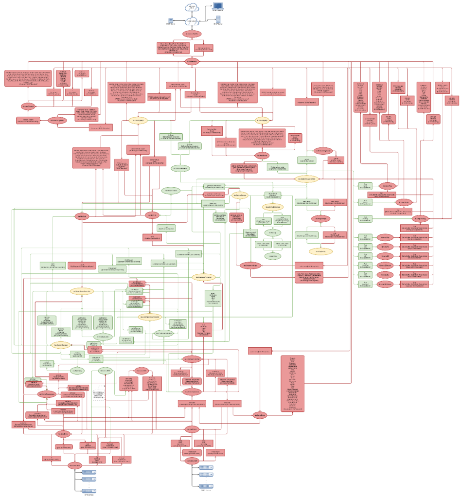
As the diagram shows, all components in the final architecture are divided into three groups as per the security goals of the system:
Red untrusted components are placed at the edge of the system; green trusted ones at the heart; yellow highly trusted ones in between.
In this arrangement, basic protection and verification were sufficient for untrusted components, because the achievement of the security goals did not depend on them. The protection and verification requirements for trusted components are certainly high, but since the trusted components are “covered” by highly trusted ones, their protection requirements could be relaxed. So only the highly trusted components, which, as you can see, were few, needed to be protected and verified to the maximum extent. The result was a heterogeneous system in which only a small fraction of highly trusted components needed to be thoroughly protected and verified.
Thanks to cyber-immunization, we not only eliminated the security issues present in the original PLC, but fundamentally changed the approach to security by embedding it at the design stage. Thus, we are now protected against not only known threats, but potential future ones, which means that administrators can sleep peacefully – now they have time to respond and install security patches, because there won’t be so many of them.
Note that the Cyber Immune practices described in this post are applicable not only to a specific device or industry, but to many other devices and industries in today’s cyber-physical world. In this sense, the Cyber Immune approach provides a concrete yet universal answer to the question of how to build highly secure systems while keeping costs at an acceptable level.
Authors:
Alexander Vinyavsky, Technology Evangelist, Kaspersky
Maxim Dontsov, Security Analysis Group Manager, Kaspersky
The use of internet of things (IoT) technologies in urban environments optimizes and automates urban processes, making cities safer, more efficient and more comfortable places to live. IoT programmable logic controllers (PLCs) can collect information from individual sensors, connected engineering systems and other equipment, and send it to cloud platforms and applications for further analytics.
At the same time as forming the boundary between the physical and digital worlds, such devices are a cybersecurity bottleneck. By hacking them, cybercriminals get to directly impact processes in the physical world, as well as gain access to, or modify, sensitive data. From the IT loop, they thus infiltrate the OT (operational technology) loop.
We took a typical PLC for a smart city and, together with the manufacturer (ISS), made it Cyber Immune, that is, guaranteed to achieve the set security goals, even under attack. This was a major step toward realizing the potential of the smart city concept, while avoiding the associated critical cyber-risks. This post explains exactly what we did and why, and how it helped to eliminate the cyber-risks.
For the hardware part, we took a fairly typical PLC with an ARM9 processor, which looked as follows:
The PLC communicated with top-level cloud platforms and applications via Ethernet, and with field devices via RS-485.
The PLC was Debian-based and designed to handle the main operation scenarios of the device:
To implement these use cases, the PLC architecture was kept quite minimal. It consisted of several components, the main one being a Mosquitto message broker for sending and receiving data via the MQTT protocol. This component formed the heart of the first build, since it channeled all information flows:
Schematically, the architecture can be represented as follows:
Looking at the PLC from a security perspective, we can identify a number of fundamental problems:
In practice, the above issues greatly increase the information security risks, as they can not only make an incident more likely, but also more damaging. The burden on the operating unit also increases – if the vendor releases a patch for a vulnerability, the administrator must respond immediately and update the device.
Our task was to make the solution Cyber Immune. That meant designing the system so that the properties we identified as important were maintained under all circumstances, even in the event of a cyberattack. To do so, we had to address the fundamental issues outlined above.
The first thing we did was to define what security meant in our particular case by posing the question: What are we protecting the PLC from? That is, we formulated the security goals and assumptions. The security goals were those invariant properties which, if achieved, would ensure the safe operation of the system in any possible use case, factoring in the security assumptions. The security assumptions consisted of additional constraints imposed on the operating conditions of the system.
Next, we designed the PLC architecture so that the stated security goals would be met without fail, taking into account the safety assumptions. To achieve this, we modified the architecture of the original PLC.
Above all, it was necessary not only to bulletproof the system at the application code level, but also at the deeper level of the operating system. For this reason, our first step in designing the architecture was to migrate the solution from Debian to KasperskyOS, which meets the requirements for out-of-the-box Cyber Immunity.
That done, we adjusted the architecture of the application part of the PLC, eliminating the fundamental architectural problems discussed above: we isolated the MQTT broker, separated the upstream and downstream data flows, and improved administration security.
The result was a Cyber Immune system guaranteed to achieve the security goals, as we have verified through multiple tests and checks.
Now let’s review the steps we went through in order.
The Cyber Immune approach is based on the Secure by Design philosophy, which states that the security of a system is not an additional requirement, but an integral part of its design. That is, security must be built in at the design stage.
At the same time, Secure by Design in its purest form says little about the specifics of how to achieve this.
This is where Cyber Immunity comes in, which adds flesh to the bones:
Putting the Cyber Immunity approach into practice, the first step was to formulate an answer to the question: What are we protecting the PLC from? That is, to explicitly describe the PLC values and potential troubles unacceptable for us – at the level of the product’s business purpose.
We realized that we needed:
These were the things that we decided must be protected from potential problems. And not from specific vulnerabilities or attack scenarios. We proceeded from the premise that “everything that can be hacked will be hacked.” That is, any violations of the aspects outlined above are unacceptable for us, be they known vulnerabilities or zero-days that appear later.
Defining what’s important for us underpins our understanding of what system security actually is. After all, there is no thing as “general security.” Security is always specific to each product depending on its business purpose and context of use. Aiming at general security means trying to make the system invulnerable by protecting every single component from every single threat (which is impossible, not least due to limited resources).
Instead, the Cyber Immune approach introduces security goals and assumptions. With this in mind, we documented the above-described values in more formal language in the form of security goals.
In summary, the security goals for the PLC look as follows:
In defining the security assumptions, we set a number of restrictions. In particular, we defined and identified:
• Constraints on physical access to the PLC
• Potential actions by internal and external intruders
• Trusted configuration sources
• Threats that we do not provide protection against (for example, we accepted that we do not protect against anthropogenic threats)
The next important step was to design the system so as to deliver the set security goals, taking into account the security assumptions. To achieve this, we modified the architecture of the original PLC. Let’s take a look at what we did and why.
Trust in the system level of the solution is essential – without it all further efforts to build a secure system as a whole will be futile. So, the first design step was to port the solution from the original Debian operating system to KasperskyOS, which meets the requirements for out-of-the-box Cyber Immunity. Due to support for most POSIX calls and the large variety of basic components in the SDK (for example, network and file subsystems), porting did not entail a complete rewrite of the entire code.
The main task that was addressed was to switch the administrative data flow (the way components interact within the solution) from the MQTT protocol to IPC (interprocess communication – the core mechanism of interaction within KasperskyOS). This solved several tasks at once:
Accordingly, the NEAT principle was observed:
• Non-bypassable – protection mechanisms cannot be bypassed
• Evaluatable – all security policies are stored inside the monitor, able to be easily analyzed and verified as correct and sufficient
• Always-invoked – security policies are applied to any interaction in the system
• Tamperproof – the system cannot be modified during operation
After protecting the system layer, we also needed to secure the solution’s application layer. This began by analyzing the central component of the whole solution: the MQTT broker.
The MQTT broker has the largest attack surface (due to its large codebase and interaction with the external network), and its correct operation underpins the whole solution. This component also implements a TLS connection – the main mechanism for secure interaction with the cloud.
What’s more, the MQTT protocol contains almost no security features: the MQTT 5.0 specification contains only general recommendations for the developer. Above all, this jeopardizes the security goal for communication with the cloud platform, but it is also a security bottleneck in attacks on other system components and, thus, a violation of the other security goals.
To increase broker security and simplify the procedure for verifying the correctness of the TLS connection, there was no need to invent some kind of on-the-spot protection; instead, we used one of the many KasperskyOS design patterns: TLS Terminator.
Design patterns are replicable architectural constructs that address common design issues within some frequently occurring context.
The TLS Terminator pattern provides for the use of a separate component to establish the TLS connection, which:
The result is the following communication pattern:
That is:
On top of that, we maintain strict control over all interactions with TSL Terminator as per the security policies, which have been flexibly configured specifically for this component.
As a result of the work carried out, the attack surface of the MQTT broker seen by an intruder in the external network was drastically reduced, and verification of the TLS connection mechanism was simplified.
The next step was to separate the flows of data coming from the cloud (control data flow) and telemetry data collected from field-level execution units (field data flow).
This was accomplished as follows:
The outcome was the following communication pattern:
As a result of the work carried out, the device was protected from attacks by an intruder in the internal network.
One of the customer’s main requirements for the smart controller was usability. For this purpose, a web server was deployed on the device, providing the administrator with a wide range of options. However, from a security perspective, the web server, like the MQTT broker, is a highly vulnerable component that requires protection.
A particularly important security goal for the PLC is to ensure secure administration of the device. But how is this administration organized? For example, when diagnosing the device status, an authorized user sends a request to the web server. The web server, in turn, forwards a diagnostic request to the components to share their status and then sends the result back to the user. When updating configurations, the web server passes the dataset to the component responsible for validating and installing the update package. So, by hacking the web server that has a large attack surface, an attacker can cause damage to other components of the solution.
By isolating the web server in a separate component, we solved multiple issues related to privilege escalation, but the question of administrator authorization remained. Most reliable is certificate-based authorization, but implementing this mechanism in the web server itself gives rise to the same issues as when using TLS in the MQTT broker.
To solve this problem, we also used the TLS Terminator pattern, but not in the client version (which establishes a connection at the request of the component), but in the server version.
The server version of TLS Terminator (also based on Mbed TLS) makes it possible to deploy a server available for connection from an external network using the TLS protocol, and then notify the hooked-up component that a connection has appeared. As a result, the most important operations related to certificate-based authorization are moved to a separate, small entity with a minimal attack surface.
Having taken all these steps, we got a product that can be described as Cyber Immune. That is, guaranteed to achieve its set security goals, given the security assumptions.
After much work to make the PLC Cyber Immune, the solution architecture was transformed from this:
To this:
As the diagram shows, all components in the final architecture are divided into three groups as per the security goals of the system:
Red untrusted components are placed at the edge of the system; green trusted ones at the heart; yellow highly trusted ones in between.
In this arrangement, basic protection and verification were sufficient for untrusted components, because the achievement of the security goals did not depend on them. The protection and verification requirements for trusted components are certainly high, but since the trusted components are “covered” by highly trusted ones, their protection requirements could be relaxed. So only the highly trusted components, which, as you can see, were few, needed to be protected and verified to the maximum extent. The result was a heterogeneous system in which only a small fraction of highly trusted components needed to be thoroughly protected and verified.
Thanks to cyber-immunization, we not only eliminated the security issues present in the original PLC, but fundamentally changed the approach to security by embedding it at the design stage. Thus, we are now protected against not only known threats, but potential future ones, which means that administrators can sleep peacefully – now they have time to respond and install security patches, because there won’t be so many of them.
Note that the Cyber Immune practices described in this post are applicable not only to a specific device or industry, but to many other devices and industries in today’s cyber-physical world. In this sense, the Cyber Immune approach provides a concrete yet universal answer to the question of how to build highly secure systems while keeping costs at an acceptable level.
Authors:
Alexander Vinyavsky, Technology Evangelist, Kaspersky
Maxim Dontsov, Security Analysis Group Manager, Kaspersky